For two-photon imaging of tissue slices, we offer a Prairie Ultima XY microscope equipped for whole-cell patch clamp recording, with an AxoPatch 1D amplifier and Sutter MP-285 computer-controlled micromanipulator (thanks to Stanford NeuroVentures funding).
If you have questions about suitability of this scope for a particular experiment, please contact us.
Note: if you plan to use this microscope, you will need to take Stanford's online laser safety training course.
Fast Facts
- One of two two-photon microscopes that share two Ti:sapphire lasers on a large optical table
- Equipped for 2-photon imaging and simultaneous 2-photon photoactivation/ablation
- Fully automated motorized stage
- Fast-scanning option for imaging at up to 25 frames per second
- Heated stage and head restraint for mice
- Solution perfusion for slices
- Vaporizer & O2 supply for on-scope anesthesia
Specifications
For a visual overview of the scanhead filters and dichroics click here.
For in-depth information on this scope, you can also access the user manual (requires SUNet ID, and a pdf file reader).
| Microscope body | The two-photon slice rig is built around an Olympus BX-61W upright microscope, with motorized focus drive. |
|---|---|
| Transmitted light | Provided as part of the BX-61W microscope body. Halogen light source with digital illumination level control buttons on the microscope body. Long working distance, 0.8 NA condenser with oblique illumination capability. Transmitted light source shuts off automatically when epifluorescence cube is set for 2P laser scanning. |
| Nosepiece | Two-position nosepiece with manual swing-out mechanism. |
| Fluorescence equipment | EXFO X-Cite 120 illumination source, coupled to scope with liquid light guide. Manual Olympus 6-position reflector turret with positions for laser scanning and, via eyepieces: brightfield, GFP and DsRed fluorescence. |
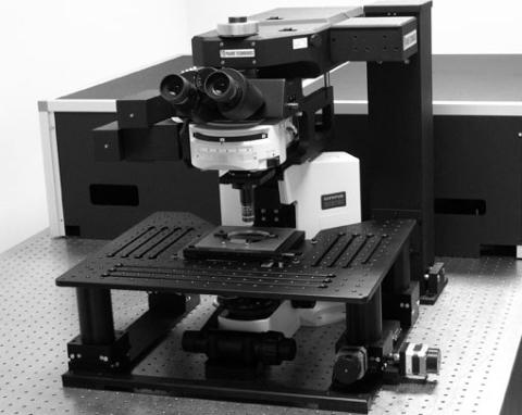
| XY stage | Large platform stage (shown in photo above) on X-Y cross roller bearings to move specimen in X and Y with respect to the fixed microscope. Height is manually adjustable over approximately 37 mm. Movements can be controlled via software or Prairie motion control interface. Smallest step size 10 nm. |
| Objectives | |||
|---|---|---|---|
| mag. | type | NA | w.d. (mm) |
| 10× | Olympus U Plan Fl N | 0.3 | 10 |
| 40× | Olympus LUM Plan Fl W/IR-2 | 0.8 | 3.3 |
| 6-position manual epifluorescence turret click here for visual overview of scanhead filters and dichroics | ||||||
|---|---|---|---|---|---|---|
| turret position | description | excitation | dichroic 50% trans. (nm) | emission | Chroma weblink | pdf file |
| 1 | 2P laser scanning | N/A | 660 | NA | N/A | 2pslprimarydichroic.pdf |
| 2 | brightfield | empty | empty | empty | N/A | N/A |
| 3 | GFP | 470/40 (peak/FWHM, nm) | 495 | 525/50 (peak/FWHM, nm) | N/A | 49002.pdf |
| 4 | DsRed | 545/30 (peak/FWHM, nm) | 570 | 620/60 (peak/FWHM, nm) | N/A | 49005.pdf |
| 5 | empty | - | - | - | - | - |
| 6 | empty | - | - | - | - | - |
Ultima XY Laser Scanning Modes
For a visual overview of the scanhead filters and dichroics click here.
| Galvo Scanning Mode | |
|---|---|
| Scanner | Two independent galvanometric scanning mirrors, real-time controlled. |
| Scan resolution | 11 × 1 to 2048 × 2048 pixels, continuously variable |
| Scanning speed | Dwell time per pixel adjustable from 0.4 to 100 μs in 0.4 μs steps. Sampling time per pixel 0.4 μs. Choice of averaging or summing mode acquisition. |
| Scan zoom | 1× to 128×, digitally variable in steps of 0.01 |
| Scan rotation | Free 360° rotation in steps of 1°, free X/Y offset. |
| Field of view | 60× objective: 235.1 μm × 235.1 μm 20× objective: 703.2 μm × 703.2 μm |
| Fast Scanning (AOD) Mode | |
| Description | This optional fast scanning mode uses AOD (acousto-optical deflector) scanning in place of the X-axis galvo. The imaging beam is directed through the AOD path via motorized switching optics on the light table. During AOD scanning, the X-axis galvo is stationary. |
| Scan speed | 28 512×512 frames per second. Higher scan speeds possible for smaller regions of interest (ROIs). |
| All Modes | |
| Detection | Dual top-mounted non-descanned detectors—hand-selected Hamamatsu multi-alkali PMTs. Transmitted light detection channel with Dodt gradient contrast detection (DIC-like imaging capability). This channel has a motorized dichroic mirror that swings into the transmitted light path so that the PMT can collect scattered/transmitted IR laser energy. This channel also has a motorized contrast adjustment. Pre-amplifier for each channel with gain, offset, and 2-pole filter bandwidth selection in software. |
| Data depth | 12-bit A/D conversion for each channel. |
Ti:sapphire lasers and table optics
| Description | This is one of two two-photon microscopes that share two Ti:sapphire lasers on a large optical table. The table optics split the beam from each laser between the two scopes. (The power to each scope can be adjusted, but the split is generally 50:50.) The actual laser power reaching the scanhead for each scope is dynamically controlled by Pockels cells (4 in all) via software interface. |
|---|---|
| Table optics | Custom table optics provide a high degree of configurability to meet a wide range of experimental needs. The imaging laser beam path can easily be switched between galvo and AOD scanning. The imaging laser can also be directed through a beam expansion path when the 20× 0.95 NA objective is used (for optimal filling of this objective's large back aperture). The uncaging laser beam path is normally directed to the uncaging galvos in the microscope scanhead. However, the uncaging beam path can optionally be redirected to the imaging galvos. This option is useful for either a) simultaneous scanning at two separate wavelengths, or b) dedicating a single laser to each microscope so that simultaneous imaging-only experiments can be carried out at (single) independent excitation wavelengths. All of these configuration options are easily obtained via electronic controls using mirrors on motorized mounts. |
| Imaging laser | Spectra Physics Mai Tai HP Deep See Ti:sapphire laser, tunable from 690 to 1040 nm. For graph of power output vs. wavelength ( 2pimglaserpowervwavelength.pdf) |
| Uncaging laser | Spectra Physics Mai Tai HP Ti:sapphire laser, tunable from 690 to 1040 nm. For graph of power output vs. wavelength( 2punclaserpowervwavelength.pdf) |
Electronics interface
| Analog inputs | 8 analog input channels are available for digitizing analog signals from experiments. |
|---|---|
| Analog outputs | 6 analog output channels are available for sending analog signals to for experimental control. |
| Digital inputs/outputs | Digital input and output channels are available for triggering data acquisition. Either the Prairie data acquisition software can run as a slave to an external program (e.g., electrophysiology data acquisition system), or the Prairie data acquisition software can run as the master control program, and send trigger signals to an external program running as a slave. |
| Control outputs | Electronic control outputs for the system devices (e.g., galvo scanning signals) are available for precise synchronization of experimental control systems. |
For more detailed information, you can access the user manual for this microscope (requires SUNet ID, and a pdf file reader).